
About Pump 8bhe
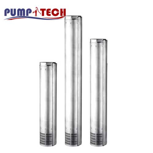
8″ semi-axial flow submerged well pump in AISI 304 and AISI 316 (hydraulic only) for deep wells, suitable for horizontal operation
Features
- Sturdy design, corrosion resistant
- Available in AISI 316
- Suitable for horizontal operation
description Pump 8bhe
8″ semi-axial flow submerged deep well pump in AISI 304 (8BHE) or AISI 316 (8BHEL) stainless steel (hydraulic only). It can be coupled with motors in water bath or oil bath.
The 8BHE(L) is specifically developed for high flow rate pumping requirements.
For further technical information see the Databook
• Water supply from deep wells
• Water distribution
• Pressurisation
• Irrigation systems
• Water treatment
• Filtration and reverse osmosis
• Industrial cooling systems
• Fountains
• Firefighting systems
Overview of technical data 8bhe
| Flow rate | Up to 126 m³/h |
| Total head | Up to 450 m |
| Max. temperature of the liquid | -5°C ÷ +60°C |
| Poles | 2 |
| Insulation class | F |
| Protection degree | IP58 (OY), IP68 (WY) |
| Voltage | Three-phase 3~380-415V ±10% OY Three-phase 3~380-415V -10%+6% WY |
| Max. immersion | 350 m with motor in water bath 150 m with motor in oil bath |
| Max. sand content | 100 gr/m3 |
Material Pump 8bhe
| Impeller | AISI 304 (EN 1.4301) AISI 316 (EN 1.4401) for version L |
| Shaft | Stainless steel 329 (EN 1.4460) |
| Outer casing | AISI 304 (EN 1.4301) AISI 316 (EN 1.4401) for version L |
| Discharge casing | AISI 304 (EN 1.4301) AISI 316 (EN 1.4401) for version L |
| Motor connection | AISI 304 (EN 1.4301) AISI 316 (EN 1.4401) for version L |
pump 8bhe
8” submersible centrifugal pump
8” submerged centrifugal electric pump, for semi-axial flow deep wells, in stainless steel AISI 304 (8BHE) or AISI 316 (8BHEL).
Developed specifically for high flow pumping needs. Discharge casing, stages and support in AISI 304 or AISI 316 depending on the model. The shaft is in AISI 329 and the impeller in AISI 316.
They can be used for water supply from deep wells, for water distribution and pressurisation, irrigation systems, water treatment, filtering and reverse osmosis, industrial cooling systems, fountains and fire-fighting systems.
Technical
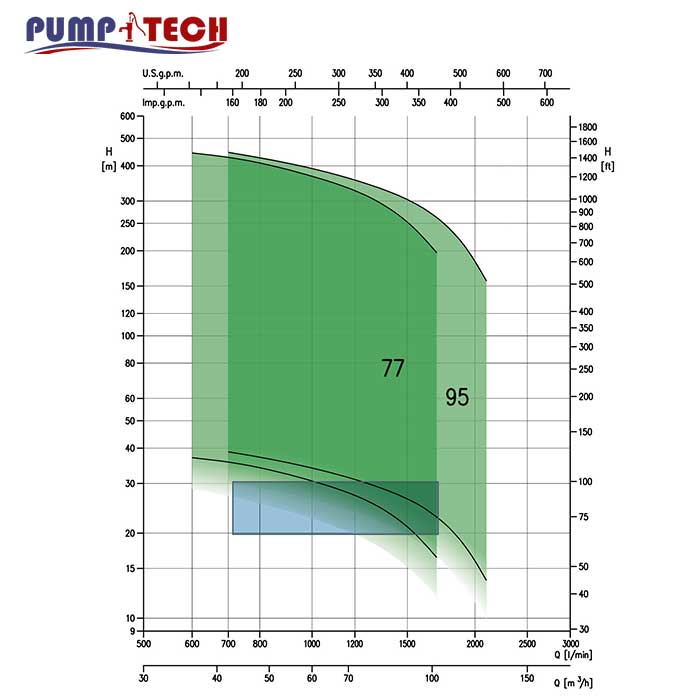
- Total head from 13.6 to 446 m
- Capacity from from 36 to 126 m3/h
- Maximum immersion: 350 m (water filled motor) 150 m
(oil filled motor) - Maximum liquid temperature 60°C
- Maximum sand content 100 gr/m3
PERFORMANCE CURVE SPECIFICATIONS
The specifications below qualify the curves shown on the following pages.
Tolerances according to ISO 9906 Annex A The curves refer to effective speed of asynchronous motors at 50 Hz Measurements were carried out with clean water at 20°C of temperature and with a kinematic viscosity of ν = 1 mm2/s (1 cSt)
The NPSH curve is an average curve obtained in the same conditions of performance curves.
The continuous curves indicate the recommended working range. The dotted curve is only a guide.
In order to avoid the risk of over-heating, the pumps should not be used at a flow rate below 10% of best
efficiency point.
Symbols explanation:
Q = volume flow rate
H = total head
P2 = pump power input (shaft power)
η = pump efficiency
NPSH = net positive suction head required by the pump
MEI = minimum efficiency index
The minimun efficiency index (MEI) is a measure of the quality of a pump size in respect to its mean efficiency. The minimum efficiency index is based on the hydraulic efficiency and on the head at the best efficiency point.
The efficiency of a pump with trimmed impeller is usually lower than that of a pump with the full impeller diameter. The trimming of the impeller will adapt the pump to a fixed duty point, leading to reduced energy consumption. The minimum efficiency index (MEI) is based on the full impeller diameter.
| Q=Capacity | Absorbed current (A) | Capacitor | KW | Pump type | ||||||||||||
| 1100 | 950 | 750 | 550 | 400 | 300 | 200 | 100 | l/min | Three-phase | Single -phase | Vc | µF | Tree-phase 230/400v 50Hz | Single-phase 230v 50Hz | ||
| 66 | 57 | 42 | 33 | 24 | 18 | 12 | 6 | m/h | 400V | 230V | ||||||
| H= Total head | ||||||||||||||||
| – | – | – | 5.1 | 6.9 | 7.9 | 8.9 | 9.5 | 2.5 | 4.4 | 6.8 | 450 | 31.5 | 1.1 | DWO 150 | DWO 150 M | |
| – | – | 5.8 | 8.6 | 10.5 | 11.5 | 12.3 | 12.7 | 3.5 | 6.1 | 9.0 | 450 | 40 | 1.5 | DWO 200 | DWO 200 M | |
| – | 7.5 | 9.7 | 11.7 | 12.9 | 13.8 | 14.5 | 15 | 4.8 | 8.3 | – | – | – | 2.2 | DWO 300 | – | |
| 7.6 | 9.8 | 12.4 | 14.3 | 15.6 | 16.3 | 16.9 | 17.5 | 6.4 | 11.0 | – | – | – | 3.0 | DWO 400 | – | |