
About Pump sf6
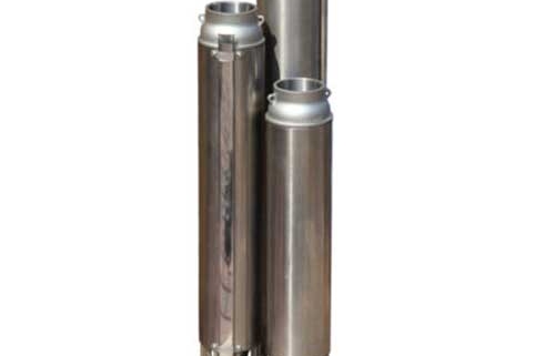
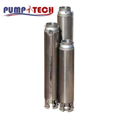
6″ submerged well pump (hydraulic only), lightweight and easily transportable. Suitable for water supply
Features
- Practical and easy to use
- Lightweight and easily transportable
- Sturdy design, corrosion resistant
description Pump sf6
6″ submerged well pump (hydraulic only), it stands out for its lightness that makes it easily transportable and can be coupled with motors in a water bath or oil bath.
The SF6, with its sturdy, corrosion-resistant design, offers a wide range of performance.
For further technical information see the Databook
• Water supply systems for civil and industrial use
• Pressure boosting systems
• Irrigation and community waterworks
Overview of technical data sf6
| Flow rate | Up to 66 m³/h |
| Total head | Up to 362 m |
| Max. temperature of the liquid | +30°C |
| Poles | 2 |
| Insulation class | F (4″ – 6″ OY), (6″ WY) B (4″ WY) |
| Protection degree | IP 58 (4″ – 6″ OY), (6″ WY) IP 68 (4″ WY) |
| Voltage | Three-phase 3~400V (±10%) Three-phase 3~400V (+6% -10%) |
| Max. immersion | 350 m with motor in water bath 150 m with motor in oil bath |
| Max. sand content | 50 ppm |
Material Pump sf6
| Impeller | PPO reinforced with glass fibres |
| Shaft | Stainless steel 420 (EN 1.4021) |
| Outer casing | AISI 304 (EN 1.4301) |
| Discharge casing | AISI 304 (EN 1.4301) |
| Motor connection | AISI 304 (EN 1.4301) |
pump sf6
6” submersible centrifugal pump
Discharge and suction casing in AISI 304. Outer casing, spacers, shim rings, non-return valve, cable protection and suction grid in AISI 304. The impellers and diffusers in PPO reinforced with glass fibres. The shaft is in AISI 420. Suitable for water supply systems for civil and industrial use, for pressurisation systems, for irrigation, aqueducts for communities.
Technical
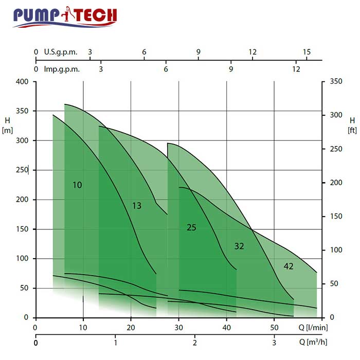
• Total head from 4 to 362 m
• Capacity from 3 to 66 m3/h
• Maximum liquid temperature 30°C
• Maximum sand content 50 ppm
• MEI > 0.4 for SF6 R10 – R13
PERFORMANCE CURVE SPECIFICATIONS
The specifications below qualify the curves shown on the following pages.
Tolerances according to ISO 9906 Annex A
The curves refer to effective speed of asynchronous motors at 50 Hz
Measurements were carried out with clean water at 20°C of temperature and with a kinematic viscosity of ν = 1 mm2/s (1 cSt)
The NPSH curve is an average curve obtained in the same conditions of performance curves.
The continuous curves indicate the recommended working range. The dotted curve is only a guide.
In order to avoid the risk of over-heating, the pumps should not be used at a flow rate below 10% of best efficiency point.
Symbols explanation:
Q = volume flow rate
H = total head
P2 = pump power input (shaft power)
η = pump efficiency
NPSH = net positive suction head required by the pump
MEI = minimum efficiency index
| Q=Capacity | Absorbed current (A) | Capacitor | KW | Pump type | ||||||||||||
| 1100 | 950 | 750 | 550 | 400 | 300 | 200 | 100 | l/min | Three-phase | Single -phase | Vc | µF | Tree-phase 230/400v 50Hz | Single-phase 230v 50Hz | ||
| 66 | 57 | 42 | 33 | 24 | 18 | 12 | 6 | m/h | 400V | 230V | ||||||
| H= Total head | ||||||||||||||||
| – | – | – | 5.1 | 6.9 | 7.9 | 8.9 | 9.5 | 2.5 | 4.4 | 6.8 | 450 | 31.5 | 1.1 | DWO 150 | DWO 150 M | |
| – | – | 5.8 | 8.6 | 10.5 | 11.5 | 12.3 | 12.7 | 3.5 | 6.1 | 9.0 | 450 | 40 | 1.5 | DWO 200 | DWO 200 M | |
| – | 7.5 | 9.7 | 11.7 | 12.9 | 13.8 | 14.5 | 15 | 4.8 | 8.3 | – | – | – | 2.2 | DWO 300 | – | |
| 7.6 | 9.8 | 12.4 | 14.3 | 15.6 | 16.3 | 16.9 | 17.5 | 6.4 | 11.0 | – | – | – | 3.0 | DWO 400 | – | |