About Pump md-mmd(4)
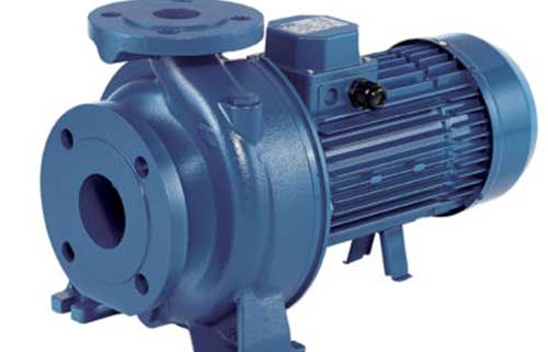
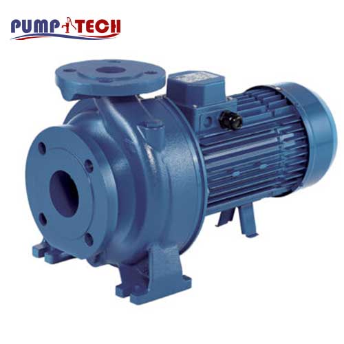
Standardised cast iron monobloc centrifugal pump with AISI 304 impeller for MD and cast iron impeller for MMD, with 2 and 4 poles motors with high energy efficiency. Equipped with a Back pull-out design that allows the motor block to be removed without having to disconnect the piping body for maintenance
Features
- Sturdy construction
Technical
- Flow rate Up to 600 m³/h
- Total head Up to 92,7 m
- Max. working pressure 10 bar
description Pump md-mmd(4)
Standardised cast iron monobloc centrifugal pump with AISI 304 impeller for MD and cast iron impeller for MMD, with 2 and 4 poles motors with high energy efficiency.
The MD and MMD electric pumps feature a back pull-out design that allows the motor block to be removed without having to disconnect the piping body for maintenance.
For further technical information see the Databook
• Heating, ventilation and air-conditioning systems
• Water supply for civil, agricultural and industrial plants
• Pressurisation
• Firefighting systems
• Industrial liquid handling systems
• Irrigation for farms, sports facilities
• Washing systems
Overview of technical data md-mmd(4)
| Flow rate | Up to 600 m³/h |
| Total head | Up to 92,7 m |
| Max. working pressure | 10 bar |
| Max. temperature of the liquid | -10°C ÷ +90°C |
| MEI | > 0.4 |
| Poles | 2 and 4 |
| Insulation class | F |
| Protection degree | IP55 |
| Voltage | Three-phase 3~230/400V ±10% (up to 4 kW included) Three-phase 3~400/690V ±10% (from 5.5kW and above for MD) (from 7.5kW and above for MMD) |
Material Pump md-mmd(4)
| Pump body | Cast iron |
| Impeller | Cast iron |
| Shaft | Stainless steel 420 (EN 1.4021) |
| Mechanical seal | Standard = Ceramic/Carbon/NBR MMD = Silicon Carbide/Silicon Carbide/NBR H = Graphite/Ceramic/FPM HS = Silicon Carbide/Silicon Carbide/FPM HW = Tungsten Carbide/Tungsten Carbide/FPM HSW = Silicon Carbide/Tungsten Carbide/FPM E = Graphite/Ceramic/EPDM |
| Motor support | Aluminium for the rest of the range |
pump md-mmd(4)
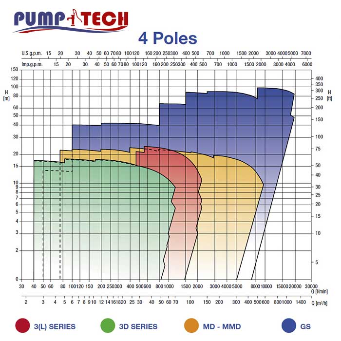
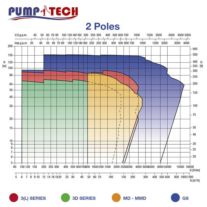
CURVE SPECIFICATIONS
The specifications below qualify the curves shown on the following pages.
Tolerances according to ISO 9906:2012 – Grade 3B The curves refer to effective speed of asynchronous motors at 50 Hz, 2 poles.
Measurements were carried out with clean water at 20°C of temperature and with a kinematic viscosity
of n = 1 mm2/s (1 cSt)
The NPSH curve is an average curve obtained in the same conditions of performance curves.
The continuous curves indicate the recommended working range. The dotted curve is only a guide.
In order to avoid the risk of over-heating, the pumps should not be used at a flow rate below 10% of best
efficiency point.
Symbols explanation:
Q = volume flow rate
H = total head
P2 = pump power input (shaft power)
h = pump efficiency
NPSH = net positive suction head required by the pump
MEI = minimum efficiency index
The minimum efficiency index (MEI) is a measure of the quality of a pump size in respect to its mean efficiency. The minimum efficiency index is based on the hydraulic efficiency and on the head at the best efficiency point.
The efficiency of a pump with trimmed impeller is usually lower than that of a pump with the full impeller diameter. The trimming of the impeller will adapt the pump to a fixed duty point, leading to reduced energy consumption. The minimum efficiency index (MEI) is based on the full impeller diameter.
The operation of these water pumps with variable duty points may be more efficient end economic when controlled, for example, by the use of a variable speed drive that matches the pump duty to the system.