
About Pump IDROGO
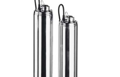
5″ submerged pump with stainless steel outer casing and glass fibre reinforced PPE impellers, built with double mechanical seal in oil chamber. Equipped with 20 metres of cable, it is easy to install and suitable for vertical and horizontal operations. The single-phase version with float switch (called “A” version) is also available on request
Features
- Silent
- Practical and easy to use
- Suitable for horizontal operation
description Pump IDROGO
5″ submerged pump with stainless steel outer casing and glass fibre reinforced PPE impellers.
The IDROGO electric pump is reliable and corrosion-resistant, also due to the technical solutions adopted in its construction, such as the double mechanical seal in the oil chamber.
This pump is easy to install because it comes with 20 metres of cable for immediate installation and is suitable for vertical and horizontal operation.
The single-phase version with float switch (called ‘A’ version) on request.
The 5 or 10-metre key float with counterweight, supplied on request, is a useful and effective accessory and allows you to control the pump’s start and stop based on the level of water present in the tank or well.
For further technical information see the Databook
- Handling of clear water from wells, cisterns and primary collection tanks
- Pressurisation of domestic systems
- Small-scale irrigation
- Vehicle washing
- Pressure boosting in general
Overview of technical data IDROGO
| Flow rate | from 1.2 to 7.2 m³/h |
| Total head | From 10 m to 76 m |
| Max. working pressure | 10 bar |
| Max. temperature of the liquid | +40°C |
| Poles | 2 |
| Insulation class | F |
| Protection degree | IP68 |
| Voltage | Single-phase 1~230V ±10% Three-phase 3~230/400V ±10% |
Material Pump IDROGO
| Impeller | PPE+PS with glass fibres |
| Shaft | Stainless steel 431 (EN 1.4057) |
| Mechanical seal | (motor side) in Carbon/Ceramic/NBR (pump side) in Silicon Carbide/Carbon/NBR |
| Outer casing | AISI 304 (EN 1.4301) |
pump IDROGO
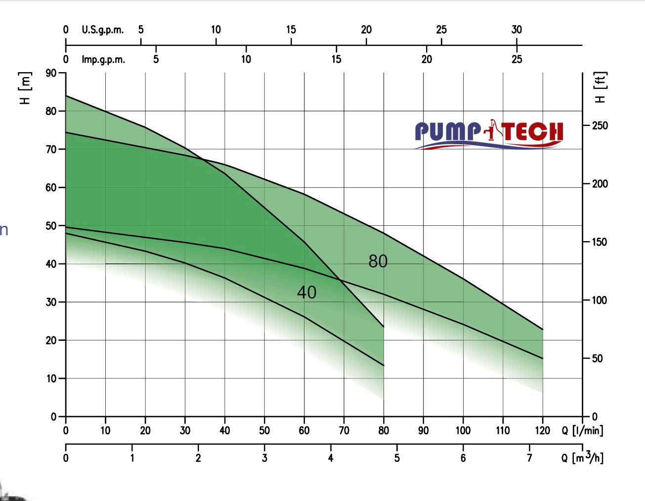
PERFORMANCE CURVE SPECIFICATIONS
The specifications below qualify the curves shown on the following pages.
Tolerances according to ISO 9906 Annex A
The curves refer to effective speed of asynchronous motors at 50 Hz
Measurements were carried out with clean water at 20°C of temperature and with a kinematic viscosity
of ν = 1 mm2/s (1 cSt)
The NPSH curve is an average curve obtained in the same conditions of performance curves.
The continuous curves indicate the recommended working range. The dotted curve is only a guide.
In order to avoid the risk of over-heating, the pumps should not be used at a flow rate below 10% of best efficiency point.
Symbols explanation:
Q = volume flow rate
H = total head
Technical
- Total head from 10.3 to 75.7 m
- Capacity from 1.2 to 7.2 m3/h
- Maximum liquid temperature 40°C
- Maximum solid size passage 2.5 mm
5” submersible centrifugal pump
External casing, motor cover, seal housing disc, filter and closing ring in AISI 304 impeller, diffuser and spacer in PPE+PS reinforced with fibreglass and shaft in AISI 431. Upper mechanical seal (motor side) in Carbon/Ceramic/NBR while the lower one (pump side) in SiC/Carbon/NBR.
Movement of clean water from wells, cisterns and tanks, the pressurisation of domestic systems, small irrigation, the washing of vehicles and increases in pressure in general.
Pump type | KW | Capacitor | Absorbed current | Q=Capacity | ||||||||||
Single-phase 230V 50Hz | Three-phase 400V 50Hz | F | V | 1 | 3 400V | l/min | 20 | 30 | 40 | 60 | 80 | 100 | 120 | |
m/h | 1.2 | 1.8 | 2.4 | 3.6 | 4.8 | 6 | 7.2 | |||||||
H=Total head | ||||||||||||||
M 40/06 | – | 0.45 | 16 | 450 | 3.8 | – |
| 33.1 | 30.8 | 27.8 | 20 | 10.3 | – | – |
M 40/08 | 40/08 | 0.6 | 20 | 450 | 4.3 | 1.9 | 43.3 | 40.2 | 36.3 | 26.1 | 13.4 | – | – | |
M 40/10 | 40/10 | 0.75 | 20 | 450 | 5.7 | 2.2 | 54.1 | 50.2 | 45.4 | 32.6 | 16.8 | – | – | |
M 40/12 | 40/12 | 0.9 | 20 | 450 | 6.8 | 2.4 | 64.9 | 60.2 | 54.5 | 39.2 | 20.2 | – | – | |
M 40/15 | 40/15 | 1.1 | 31.5 | 450 | 7.3 | 3.0 | 75.7 | 70.3 | 63.6 | 45.7 | 23.5 | – | – | |
M 80/12 | 80/12 | 0.9 | 20 | 450 | 6.4 | 2.3 | – | 45.6 | 44 | 38.8 | 32 | 23.2 | 15.2 | |
M 80/15 | 80/15 | 1.1 | 31.5 | 450 | 7.5 | 3.1 | – | 57 | 55 | 48.5 | 40 | 28 | 19 | |
– | 80/20 | 1.5 | – | – | – | 3.5 | – | 68.4 | 66 | 58.2 | 48 | 34.8 | 22.8 | |