
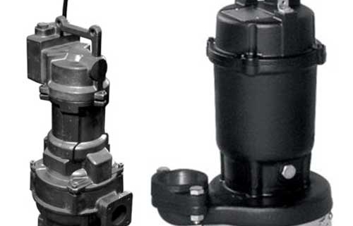
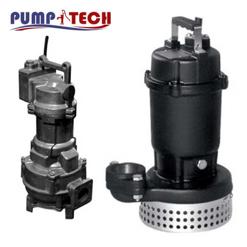
About Pump DS – DSF
Submersible pump with semi-open impeller with cast iron shim and anti-clogging filters, supplied as standard with the thermal protector and double mechanical seal with oil chamber. Suitable for pumping clear water and rainwater
Features
- Possibility to use in fixed and mobile installations
- Non-clogging filter
- Adjustment semi- open impeller
description Pump DS – DSF
Submersible pump with semi-open impeller with cast iron shim and anti-clogging filters that provide high efficiency.
The thermo protector supplied as standard in the range and the double mechanical seal with oil chamber prevent damage from dry running of the pump.
For further technical information see the Databook
- Drainage
- Domestic irrigation (e.g. gardens)
- Pumping of rainwater and clear water
Overview of technical data DS – DSF
| Flow rate | Up to 84 m³/h |
| Total head | Up to 43 m |
| Max. temperature of the liquid | +40°C |
| Poles | 2 |
| Max. solids passage | 5 mm (50DS) 6 mm (65DS) (40DSF 1.5, 1.9 kW) 7 mm (80DS) (40DSF 6 kW) 8 mm (100DS) |
| Insulation class | F for DS H for DSF |
| Protection degree | IP68 |
| Voltage | Three-phase 3~380-415±10% (DS) Single-phase 1~230±10% (DSF) Three-phase 3~400/690±10% (DSF) |
| Max. immersion | up to 1.5kW: 3 m with 6 m cable over 1.5kW: 7 m with 10 m cable |
| Max. length of fibres | 50 mm |
Material Pump DS – DSF
| Pump body | Cast iron |
| Impeller | Cast iron |
| Shaft | Stainless steel 403 (EN 1.4006) (DS) Stainless steel 420B (EN 1.4028) (DSF) |
| Mechanical seal | Impeller side: Silicon Carbide/NBR Motor side: Carbon/Ceramic/NBR (6 kW and above for DSF) |
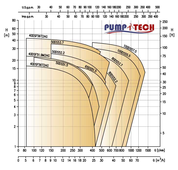
pump DS – DSF
PERFORMANCE CURVE SPECIFICATIONS
The specifications below qualify the curves shown on the following pages.
Tolerances according to ISO 9906 Annex A
The curves refer to effective speed of asynchronous motors at 50 Hz
Measurements were carried out with clean water at 20°C of temperature and with a kinematic viscosity
of = 1 mm2/s (1 cSt)
The continuous curves indicate the recommended working range. The dotted curve is only a guide.
In order to avoid the risk of over-heating, the pumps should not be used at a flow rate below 10% of best efficiency point.
Symbols explanation:
Q = volume flow rate
H = total head
P2 = pump power input (shaft power)
n = pump efficiency
Submersible electric pumps with semi-open impeller
Submersible electric pumps with semi-open impeller for clear water
and rainwater in cast iron.
Pump body, semi-open impeller, cast iron (bend) elbow. Shaft in
AISI 403 (DS) and AISI 420B (DSF).
The mechanical seal is:
– SiC/SiC/NBR (impeller side)
– Carbon/Ceramic/NBR (motor side) (from 6 kW and higher for DSF)
– Upper and lower sealing ring for DS
Technical
- Total head from 0.8 to 43 m
- Flow rate 5 to 84 m3/h
- Maximum liquid temperature 40°C
- Maximum solid size passage:
– 5 mm (50DS)
– 6 mm (65DS) (40DSF 1.5, 1.9 kW)
– 7 mm (80DS) (40DSF 6 kW)
– 8 mm (100DS) - Maximum length of 50mm fibrous
bodies (all DS models)
INSTALLATION
The versatility of use of DS – DSF electric pumps makes them installable in different applications: drainage tanks, rainwater lifting, emptying of basins or clear water lifting even with small parts in suspension thanks to the use of the high efficiency semi- open impeller. Moreover, among the features that make these electric pumps adaptable to the various uses, there is also the possibility of use in both fixed and mobile installations
| Pump type | Motor | Q=Capacity | |||||||||||||||||||
| kW | HP | l/min | 0 | 100 | 150 | 200 | 250 | 300 | 400 | 450 | 500 | 550 | 600 | 700 | 800 | 950 | 1000 | 1200 | 1250 | 1400 | |
| m/h | 0 | 6 | 9 | 12 | 15 | 18 | 24 | 27 | 30 | 33 | 36 | 42 | 48 | 57 | 60 | 72 | 75 | 84 | |||
| H=Total Head | |||||||||||||||||||||
| 50 DS 5 1.5 | 1.5 | 2 | 24.0 | 22.3 | 20.7 | 18.8 | 16.5 | 14.0 | 8.5 | – | – | – | – | – | – | – | – | – | – | – | |
| 50 DS 5 2.2 | 2.2 | 3 | 27.0 | – | 25.2 | 23.7 | 22.1 | 20.4 | 16.6 | 14.4 | 12.0 | 9.4 | – | – | – | – | – | – | – | – | |
| 50 DS 5 3.7 | 3.7 | 5 | 37.4 | – | 35.3 | 34.2 | 32.9 | 31.4 | 27.7 | 25.7 | 23.5 | 21.1 | 18.6 | – | – | – | – | – | – | – | |
| 65 DS 5 1.5 | 1.5 | 2 | 18.0 | – | 17.5 | 17.1 | 16.5 | 15.7 | 13.5 | 12.0 | 10.3 | 8.5 | 6.6 | – | – | – | – | – | – | – | |
| 80 DS 5 2.2 | 2.2 | 3 | 22.0 | – | – | 20.8 | 20.2 | 19.4 | 17.6 | 16.4 | 15.0 | 13.4 | 11.8 | 8.3 | – | – | – | – | – | – | |
| 80 DS 5 3.7 | 3.7 | 5 | 27.5 | – | – | – | 26.3 | 25.8 | 24.6 | 23.7 | 22.8 | 21.8 | 20.6 | 17.8 | 148 | 9.9 | – | – | – | – | |
| 100 DS 5 5.5 | 5.5 | 7.5 | 31.6 | – | – | – | – | 30.7 | 30.0 | 29.5 | 29.0 | 28.4 | 27.8 | 26.3 | 24.5 | 21.3 | 20.0 | 13.6 | 11.6 | – | |
| 100 DS 5 7.5 | 7.5 | 10 | 39.2 | – | – | – | – | – | 37.0 | 36.6 | 36.0 | 35.5 | 34.8 | 33.4 | 31.7 | 28.5 | 27.3 | 21.4 | 19.7 | 13.2 | |