
Main applications wkln
- Ash removal
- Boiler circulation
- Boiler feed systems
- Building services
- Cooling water and condensate
- Energy
- Flue gas desulphurization plants (FGD)
- Flue gas desulphurization systems (FGD)
- Irrigation
- Mining
Main applications wkln
- Power Stations < 100 MW
- Power Stations > 100 MW
- Pressure boosting, fire fighting systems
- Process
- Rainwater utilization
- Steam circuits
- Swimming pools
- Turbine oil supply
- Water supply
- Water transport
- Water treatment
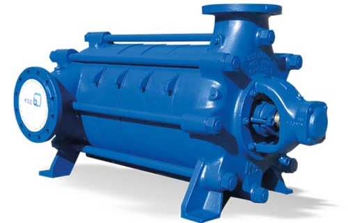
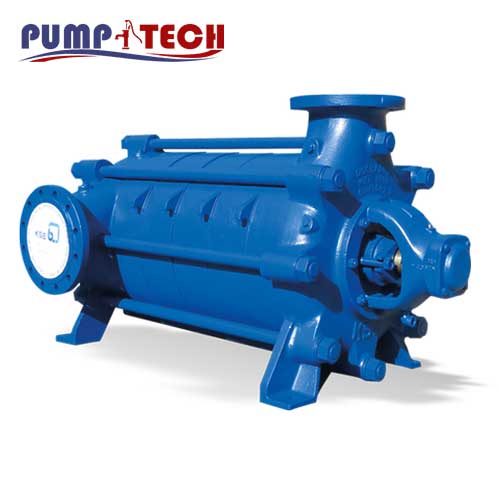
Design wkln
Horizontal high-pressure centrifugal pumps in ring sectional design, single- or multistage, vertically split suction, discharge and stage casings.
Application pump wkln
Municipal and industrial water supply in water works, pressure boosting installations, irrigation and sprinkler plants; as boiler feed pumps and condensate pumps, cooling water and hot water circulation pumps; for high pressure water in hydraulic presses, as fire pumps etc.
Drive pump wkln
Direct drive by electric motor through a flexible coupling.
The suction end of the pump is the driving end, direction of rotation is clockwise; the shaft stub of the driver is fitted on the discharge side (direction of rotation is counterclockwise), or two shaft stubs can be provided, one at each end.
Desing Details pump wkln
Construction
Horizontal high pressure centrifugal pumps in ring sectional design, single- or multistage, vertically split suction, discharge and stage casings. The individual casing parts are sealed by O-rings and are clamped together by external tie bolts.
The pump feet are cast integrally with the suction and discharge casings, and are arranged beneath the pump.
Bearings
The bearings are enclosed in two bearing housings, flanged onto each end of the pump. On the suction end of all pump sizes a cylindrical roller bearing with spacer sleeve is fitted; on the discharge side of 32 and 40 a deep groove ball bearing, 50 and up an angular ball bearing is fitted.
The rotating assembly is hydraulically balanced by means of back vanes or balance holes at the rear of the impeller; the residual axial thrust being absorbed by a ball bearing at the discharge side.
Shaft Seal
The shaft is fitted with renewable protective sleeves in the region of the stuffing box.
Uncooled soft-packed stuffing boxes are used for temperatures up to 110ºC (230ºF); for temperatures above 110ºC (230ºF) up to 140ºC (285ºF) a cooled soft-packed stuffing box is used, where the temperature on the stuffing box is kept within permissible limits with the aid of the cooling liquid. Furthermore, special stuffing boxes for connection of seaIing liquid from an outside source are available.
Uncooled mechanical seal up to 110ºC (230ºF) maximum.
Nozzle orientation
The suction nozzle is horizontal, right-hand side when viewed from driving end, and the discharge nozzle is top, vertical.
The suction flange is machined according to DIN 2533, NP 16 or BS 4504 table 16/11. The discharge flange is machined according to DIN 2535, NP 40 or BS 4504 table 40/1.