
About Pump DWC
Centrifugal pump fitted with a closed radial flow impeller in AISI 304 stainless steel. It is equipped with an insulating shell as standard, which prevents condensation inside the system. It is available with special seals for heavier duty use and higher liquid temperature limits. The choice of connections, Victaulic (DWC-V) and threaded (DWC-N), facilitates installation.
Features
- Compact dimensions
- Sturdy construction
- Silent
description Pump DWC
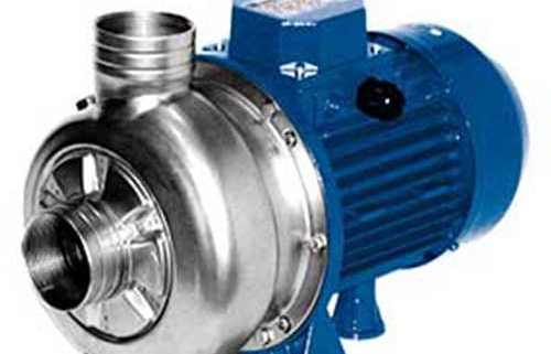
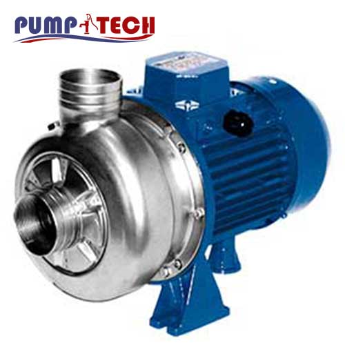
Centrifugal pump fitted with a closed radial flow impeller in AISI 304 stainless steel.
It is sturdily built, made using the exclusive hydroforming process, and is equipped with increased discharge due to the absence of additional fittings.
It is equipped with an insulating shell as standard, which prevents condensation inside the system, and the standard mechanical seal is in Ceramic/Carbon/EPDM. The DWC centrifugal pump is available with special seals for heavier duty and higher liquid temperature limits.
The choice of connections, Victaulic (DWC-V) and threaded (DWC-N), facilitates installation.
For further technical information see the Databook
- Cooling, air conditioning and heating systems
- Chillers
- Washing systems
- Civil and industrial water supply
Technical
- Total head from 25 to 6.2 m
- Capacity from 6 to 45 m3/h
- IE3 high efficiency motors starting from 0.75 kW
- Liquid temperature:
- from -15°C to +90°C (from -15°C to +110°C for
H, HS, HW and HSW versions) - Threaded or Victaulic connections
Overview of technical data DWC
| Flow rate | from 6 to 45 m³/h |
| Total head | From 6.2 to 25 m |
| Max. working pressure | 8 bar |
| Max. temperature of the liquid | 15°C ÷ +90°C for std version -15°C ÷ +110°C for H, HS, HW, HSW versions |
| Poles | 2 |
| Insulation class | F |
| Protection degree | IP55 |
| Voltage | Three-phase 3~230/400V ±10% |
Material Pump DWC
| Pump body | Stainless steel AISI 304 (EN 1.4301) |
| Impeller | Stainless steel AISI 304 (EN 1.4301) |
| Shaft | Stainless steel AISI 304 (EN 1.4301) (part in contact with the liquid) |
| Mechanical seal | Standard = Ceramic/Carbon/EPDM H = Graphite/Ceramic/FPM HS = Silicon Carbide/Silicon Carbide/FPM HW = Tungsten Carbide/Tungsten Carbide/FPM HSW = Silicon Carbide/Tungsten Carbide/FPM |
| Motor support | Aluminium |
pump DWC
Closed impeller centrifugal electric pumps in stainless steel AISI 304
Centrifugal surface electric pumps with molded AISI 304 body, obtained through the hydroforming
process: this process exploits the water pressure to deform the material. This guarantees the highest
quality standards, the drastic reduction of welding points, the ability to shape the pump body ensuring
the most efficient form absolutely and the ability to work steel with high thickness ensuring maximum
construction strength. It mounts the closed radial flow impeller and is available both with threaded
connections (DWC-N), and with victaulic connections (DWC-V) that make it suitable for installations in
chillers or in hydronic groups.
The standard mechanical seal is made of Ceramic/Carbon/EPDM, but the product is available with
special seals for harder applications and higher liquid temperature limits
CURVES SPECIFICATIONS
The specifications below qualify the curves shown on the following pages.
Tolerances according to ISO 9906:2016 – Grade 3B
The curves refer to effective speed of asynchronous motors at 50 Hz, 2 poles.
Measurements were carried out with clean water at 20°C of temperature and with a kinematic viscosity
of n = 1 mm2/s (1 cSt)
The NPSH curve is an average curve obtained in the same conditions of performance curves.
The continuous curves indicate the recommended working range. The dotted curve is only a guide.
In order to avoid the risk of over-heating, the pumps should not be used at a flow rate below 10% of best efficiency point.
Symbols explanation:
Q = volume flow rate
H = total head
P2 = pump power input (shaft power)
h = pump efficiency
NPSH = net positive suction head required by the pump
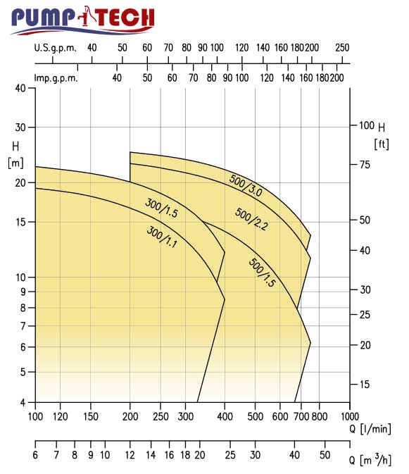
| Q=Capacity | power | Pump type | ||||||||||||
| 750 | 700 | 600 | 500 | 400 | 350 | 300 | 250 | 200 | 150 | 100 | l/min 0 | HP | kw | |
| 45 | 42 | 36 | 30 | 24 | 21 | 18 | 15 | 12 | 9 | 6 | m/h 0 | |||
| H= Total head | ||||||||||||||
| – | – | – | – | 8.5 | 11 | 13.1 | 15 | 16.6 | 18.1 | 19.2 | 21.0 | 1.5 | 1.1 | DWC 300/1.1 |
| – | – | – | – | 12 | 14.6 | 16.7 | 18.5 | 20.1 | 21.4 | 22.5 | 24.5 | 2 | 1.5 | DWC 300/1.5 |
| 6.2 | 7.4 | 9.8 | 12 | 14 | 14.9 | 15.7 | 16.4 | 17 | – | – | 18.5 | 2 | 1.5 | DWC 500/1.5 |
| 11.5 | 13 | 15.5 | 17.8 | 19.8 | 20.7 | 21.5 | 22.3 | 23 | – | – | 24.5 | 3 | 2.2 | DWC 500/2.2 |
| 13.6 | 15 | 17.6 | 20 | 22 | 22.9 | 23.7 | 24.4 | 25 | – | – | 26.3 | 4 | 3 | DWC 500/3.0 |